T9 (Scorpio) Gearbox disassembly and
re-assembly
|
As
mentioned above, the 3.36:1 1st gear ratio replacement was something I
had been wanting to do for a long time, esp. because of the 2.0ltr
Zetec's
torque. As far as a do-it-at-home
project, this is quite doable without major tools. Some key
items you'll need are a clean place to work (I use a small wooden
platform on wheels), and lots of trays for parts. Be careful of the
sychromesh assemblies and keep them "in-tact" if you can. If the
springs and keys do come out, clean and dry your hands otherwise on
reinsertion the
keys may fly all over the place. Note they are gear specific.You will
be greatly helped by having
an air compressor and airwrench - 70..80psi / 1/2". Get the best
snap ring tool(s) you can get, the box is
designed around these, inside, outside, eyed, they are all there and
there are many of them.
For the friction fitted speedo gear removal, you'll need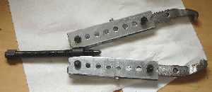 to
modify a
standard gear puller
with some extensions - I used four strips to extend the puller
arms. Make
sure to note the exact gear location, as it's a friction fit, and it
needs
to go back exactly where you found it. to
modify a
standard gear puller
with some extensions - I used four strips to extend the puller
arms. Make
sure to note the exact gear location, as it's a friction fit, and it
needs
to go back exactly where you found it.
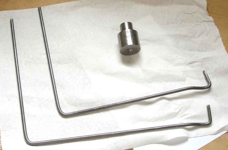
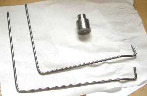
To get the bearing / sandwhich plate to come off, after removing the
snapring (!), you will need two fabricated 3/16" rods, shaped as shown.
Flatten the ends like blades as shown, as well as the small Z-bends.
Dimensions are about 8..9 inches per side.
To replace the Torrington bearing (layshaft / output side), the outer
ring just slips off, once the large nut has been removed from 5th gear.
Engage 2
& 3th gear or 1st and 3rd and use a 1/2" air wrench for this,
70..80psi. Then a heavy duty puller will be needed to get 5th gear to
come off. I used a little stub (see pic) under the puller to insert
into the hollow layshaft with .780" diameter on
the small end, but a 3/4" socket extension will work as well. Remove
the synchromesh before removing the 5th gear nut to avoid damage to the
synchro. The 5th gear nut requires a 12pt socket. The gear will likely
have hammered in a bit onto the splines. When using the airwrench to
remove it go easy, as 12pt sockets are never robust. To get the gear
off, properly place the puller hooks, but avoid the gear teeth to avoid
burring. It'll take some force.
For lubrication,
I've tried a number of different brands and viscosities, but settled on
Redline MTL,
which is a special blend of lightweight oil with synchromesh action
promoting
behaviour! This is critical, and really helps in a 7 where you'd be
likely to shift quick. It stops the notorious 2-3 crunches when the box
gets hot (Mobile 75/90 synthetic gear-oil lets go here) on the track. I
also put this in my old '84 Esprit and it transformed that gearbox.
It's
well worth the added cost (about 2x that of regular synthetic gear oil).
Anything I'd do different: I'd certainly avoid machining past the end
of the case like I did. In retrospect Brian Hill's notes were clear,
but I misinterpreted his drawing. Of course after it's all done, it's
all clear as always. No problem really, as my alternate
solution with the oilite thrust washer has been working fine for
thousands of miles and some
track time. Meanwhile, it's winter of '06/'07 now and BGH was good
enough to sell me
another T9 Scorpio case and I'll be putting that in, as soon as it
warms up here a bit. We've been below -15C for over a month now, and
working in the non-heated garage is challenging. Once it get's warm
here, like anything above
-5C, I'll go back in there and replace the case, to make it all proper
again. Nevertheless, the upgrade has been excellent and it's well
worth the time and $ spent on it.
|
|
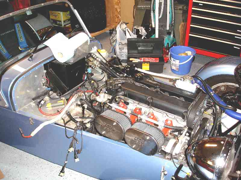
The pictorial log for
my 2005 winter upgrade
|
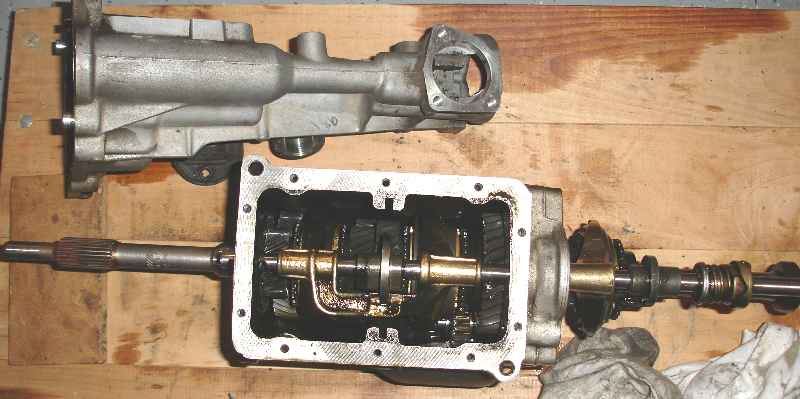
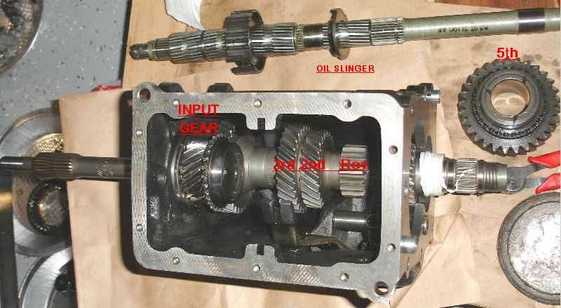
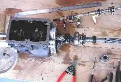
 speedo
gear, and 5th gear/synchro are located in the tail section speedo
gear, and 5th gear/synchro are located in the tail section
|
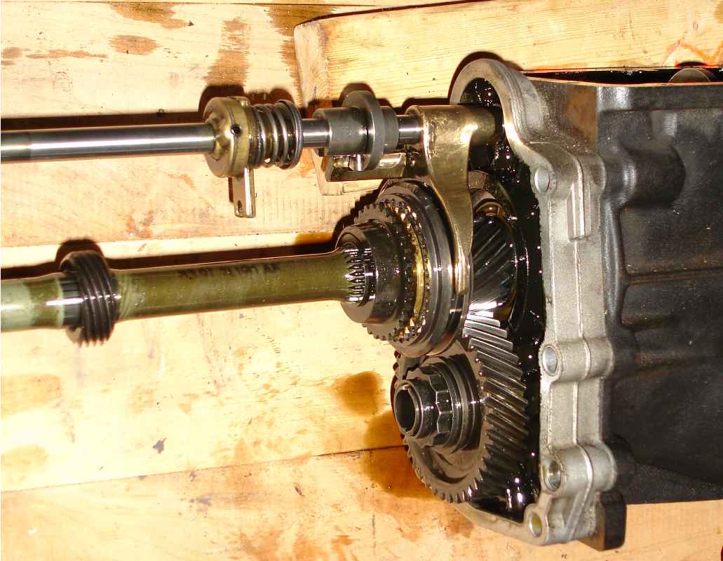
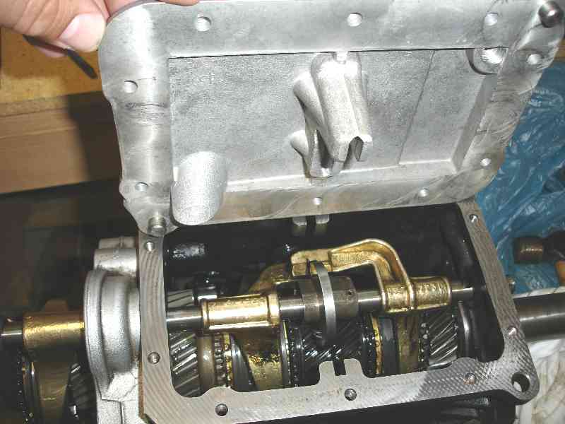
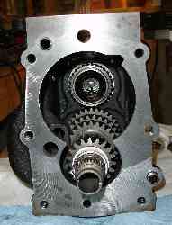
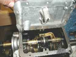
5th gear pair & Shift mechanism.
- Top shaft left-of-center, the brass disc/disc-arm & coil spring
arrangement provide the left-right location of the shift lever for the
for-aft planes for Reverse / 1-2 / 3-4 / 5th. The brass arm straddles
or forks a
pin in the tail housing.
- The steel sleeve and disc on the top shaft, right-of-center allows
for selection of
5th gear and provides lockout when other gears are engaged.
|
|
|
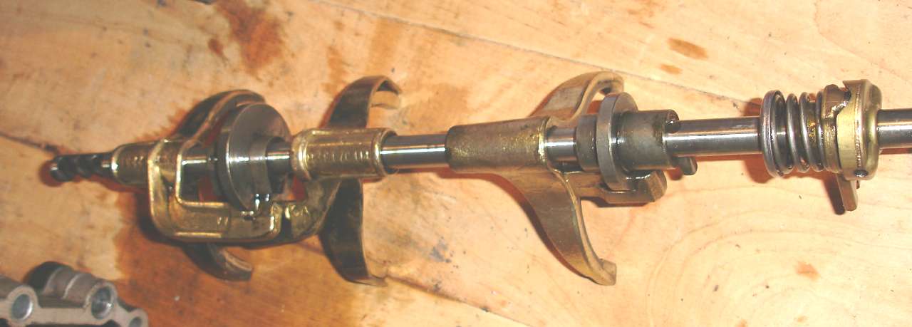
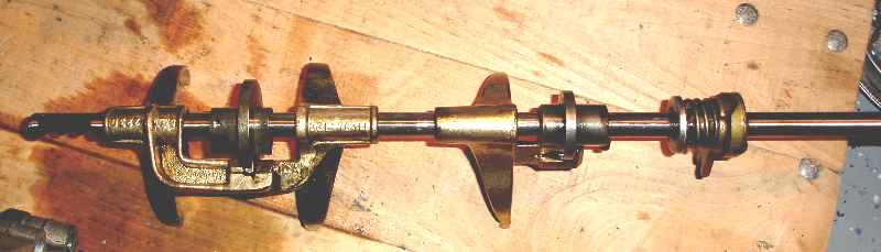
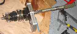
Complete
shifter mechanism.
Left to Right:
- Far-left on-shaft - indentations for:
[2-4], [Neutral], [R-1-3-5]
- 4-3 shift fork, lockout disc
(disc is located by the cover plate)
- 2-1 shift fork, 5th
shift fork
- 5th gear lockout disc
- L/R plane springload fork (far right)
(the
spring reference is located by a pin in the tailhousing) |
|
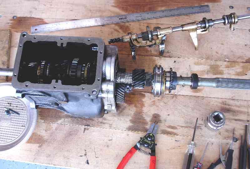
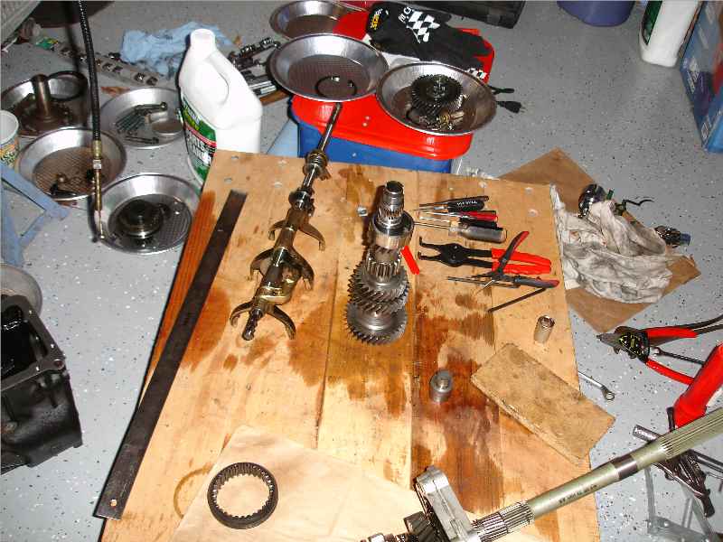
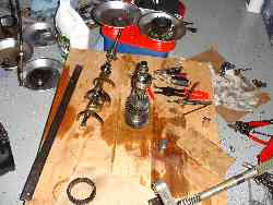
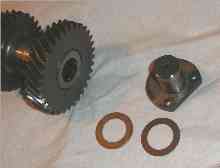
Lower-left
in the pie-tin: pin&spring
for locating shifter-shaft.
Center-right:
speedo gear (194mm
from gear back to sandwich plate
face).
Pull off with extended (fabricated) puller.
Low-center: get the
best clip/snap
ring pliers you can find!! This box has
many external and internal snap rings.
Note: 5th gear shift cone engages by moving away from 5th gear, as it's
plane is with gears 1/3/5. The cuff rides on an extension of 5th gear.
|
|
|
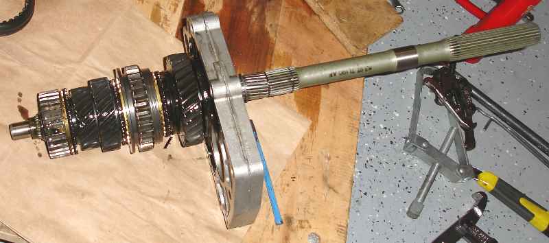
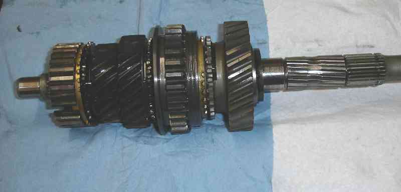
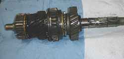
Mainshaft ( = output shaft):
Left to Right:
- Synchro slider 3-4 gear
- baulk ring 3rd gear - 3rd gear
- 2nd gear - baulk ring 2nd
- 1-2 shift ring (accepts shift fork) / Rev. gear teeth
- baulk ring 1st - 1st gear
- Sandwich plate (holds bearings)
- cleaned off output shaft (5th & speedo removed)
|
|
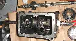
First the
layshaft stub shaft must be removed, by pounding it out through
the
hollow layshaft. I used a 10" 1/2" socket wrench extension.
To remove the layshaft (center / vertical), the outer race and rollers
of the torrington bearing in the s.w. plate have to be pushed out. With
two L-shaped 1/4" steel rods (Brian's suggestion), with the ends about
1" long and the "handles" about 9" long, the bearing outer race edge
can be pushed out between the s.w. plate and the case. The s.w. plate
can be moved out, about 1/2" inch. Then the layshaft can be lowered and
the input shaft removed. Up to this point it's been caught behind the
layshaft input gear.
|
|
|
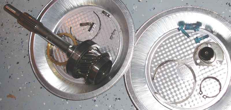
Input shaft
(left).
Showing the input shaft, main bearing and input gear, and 4th gear
synchro teeth & cone.
Note: the 4th gear synchro connects the input shaft with the output
shaft, for a 1:1 ratio.
Also, in the left tray are synchro spring, blocker pins and a baulk
ring.
In the right tray, some snap rings and the layshaft stub shaft. A
roller bearing in the layshaft runs on that.
|
|
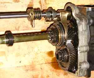
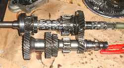
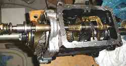
Showing the old 3.36 1st gear and
layshaft meshed. Note the input shaft is on
the left,
then the common (input) gear pair drives the layshaft permanently, as
the output shaft is referenced via a pilot bearing right next to the
common gear.
The 1st gear pair is on the right. Gears on layshaft:
Common - 3 - 2 - R - 1 (5th is removed).
|
|

|
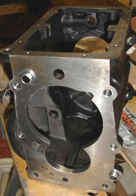
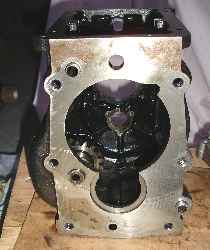
Main case
(cast iron).
Note round disc magnet at the bottom of the case.
The reverse idler gear has not been removed yet.
|
|
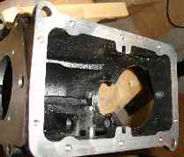
This side
mates with the sandwich (bearing) plate, and requires some machining:
The larger 1st gear on the layshaft (bottom opening) interferes with
the edge of the lower opening, as well as with some ribs on the inside
just below the reverse gear stop.
I used a boring bar set to 2.5" diameter. as suggested by BGH, and then
cut material side to side by .15"
|
|
|
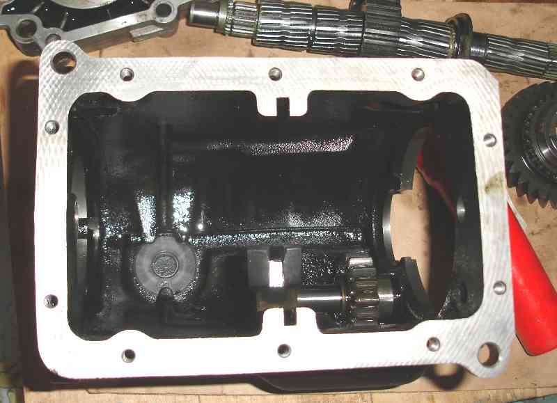
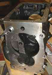
Case inside
view after machining. Note material removal at the bottom (low-center
in pic).
Need to be careful with the small reverse gear stop, that can easily be
nicked during the grinding process. The spring on the reverse idler
gear fork, keeps the idler gear located towards the rear of the box,
against the stop.
|
|
After
machining.
After washing the box, it's ready for test fitting and reassembly.
---- Ok, something went wrong here, as I
machined out the thrust
surface for the torrington bearing, the one that sits on the layshaft
in the sandwhich plate. It is held captive by the snapring in the
sandwhich plate and the case on the other side. But since I machined it
out to the full thickness, no edge remains for the bearing to rest
against - my solution is a new
thrust surface made with a bronze washer and stainless shim at the
other end of the layshaft - pics to follow below - yup, I screwed up,
but it's fixed ....(see below)
|
|
|
Test fit of
the layshaft. I used teflon tape to protect the inner race of the
Torrington bearing which was heat shrunk onto the layshaft (thanks to
John H. for calculating the correct temperature, and use of his oven!).
Note the rear side of the input shaft on top.
The layshaft stub shaft is used on the other side, to position the
layshaft more or less in the correct location.
|
|
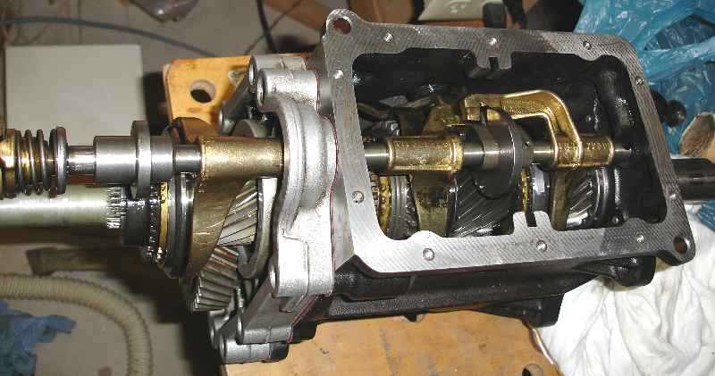
Another
testfit view from the top, showing the input shaft more clearly.
Mainshaft shown in the top of the picture.
|
|
|
Main shaft
cluster, left to right:
3/4 shifter cuff hub then 3rd gear, 2nd gear
Reverse on top of 1/2 shift cuff
note: engaging R is
accomplished by sliding the
Reverse idler gear, not this 2/3 cuff.
Next is the new 1st gear.
New brass baulk rings are in place for 1/2/3rd. The 4th and 5th showed
no measurable wear and mated well.
|
|
Reassembled,
new 1st and 5th gear, overall slightly closer ratio's for 2 and 3 as
well, due to the changed input gear on the layshaft.
New synchro rings (brass baulk rings) as well as fresh bearings.
Turned out the bearings were like new. I wasn't sure what state they
would be in as at the point of dissassembly I had put 60k miles on the
box (and the car :-).
|
|
|
New alloy
cover with top filler and oil level dipstick (see threaded entry top
right of the cover in this pic).
Note the slotted guide for the shift mechanism disc in the center of
the top plate, which
means test shifting without the cover in place, requires some care.
|
Ok,
so now I'm making it
right again -
following a couple pics
of the new thrust washer solution. Better would have probably
been, not to machine out the whole opening, but this is certainly a
lot more fun!
Also
note that late(r) model T9 (Scorpio) gearboxes are very hard to come by
in
the US. |
I
tried to find another gear case, but in the US no-one appears to have
one.
The main difference between these boxes is that the older style has a
support shaft running through the layshaft, which then runs on that. In
the newer (Ford Scorpio style) box, the layshaft hangs on a small stub
shaft (see below).
- 1/07 - Got another case - I'll swap it in sometime in the coming
months. Right. Way way too busy. I really should retire sometime.
note: it's almost 2011
and that fresh case still sits under a desk. meanwhile the gearbox is
still fine.
|
|
The
layshaft input side bearing in the older case is a set of roller
pins, which have to be temporarily glued into the layshaft with some
thick bearing grease. The newer vesion uses a caged roller bearing that
is pressed into the end of the layshaft. I believe this bearing
actually works both for the newer as well as the older boxes.
Then, the other big difference is the 5th gear selector blocker which
is much simplified in the newer box. |
I
would think (I need to test this
some day) that a later style tail and sandwhich plate should fit with
an older
case. So, if my thrust bearing solution wears out prematurely, that's
what I'll try do. |
|
Left to Right:
a. Layshaft with inserted caged roller bearing
b. bronze oillite .062" washer
- with it's ID milled out to .950"
c. stainless shim washer .010"
d. stub shaft that bolts to the front of the case.
|
|
Note: the plate with the three
holes will be shimmed on the outside, to allow for the slight laternal
shift created by the washers. The longitudinal force is taken between
the layshaft / washers / inside gearbox wall, instead of the torrington
bearing, which resting-edge I accidentially machined away..
|
Same as on the
left, but
showing the relative position of the washers. The .010" stainless shim
/ washer will
rest against the raised area on the case that exists where the stub
shaft protrudes
the front panel of the gearcase inside the box.
The gap is where the case wall will be (ok, that sounds confusing...).
Note the three bolts will be outside on the front face of the gearbox.
Purpose of the .010" washer is to
provide a smooth
running surface for the bronze washer. The oil feed is
from the opposite end of the hollow layshaft and thus these washers
will run semi-submerged in oil.
|