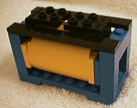
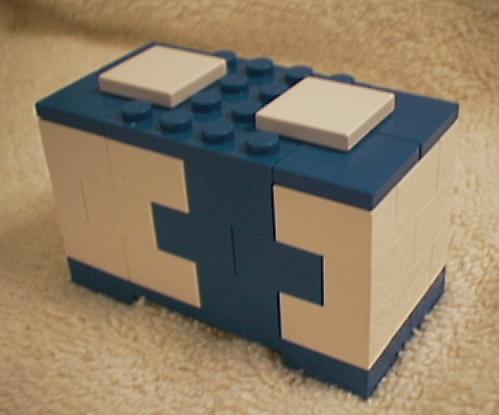
Some containers I made
The next few pictures are of an auto carrier. It's not as good as I'd like but it will keep the new cars moving along nicely
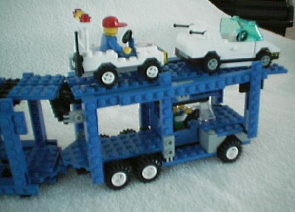
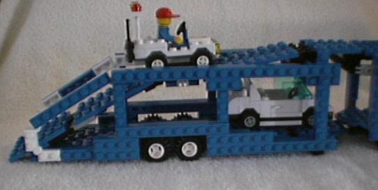
I built this to go with my new autorack train car, and my older auto carrier tractor and trailer. Calculating the pneumatic throw and lever lengths drove me crazy!! I guess a good ME would have swoped it out in no time but I fiddled for a good 10 hours to get a mechanism that was close to right. It's still not perfect. I need a good lever calculation program.
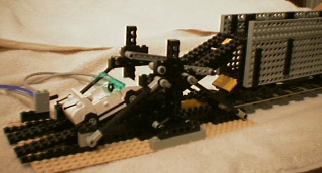
Coupling the train car to the rack ensures stability. This is prototypical.
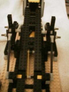
The grey levers swing from about 45 deg down to almost horizontal. That swing moves the upper end of the rack from the lower position to the upper position with little gap and no clearance problems. The yellow actuator piston is visible. Its butt end nestles below the coupler. Retracted is in the upper position, extended in the lower.
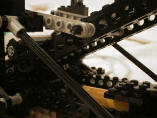
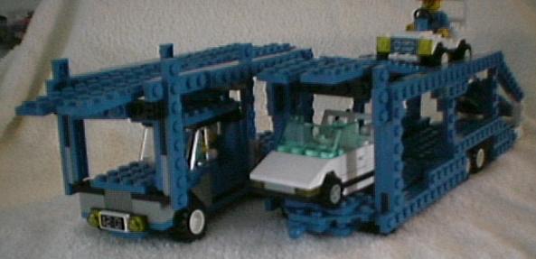
Here you can see the actuator and the lever that pulls the lower end of the rack. The rubber band holds the lower end of the rack flush against the sliding rails, without it, it has a tendency to rise up. As noted before, the grey levers move the upper end in the correct arc. Some of the ramp parts have been removed for clarity.
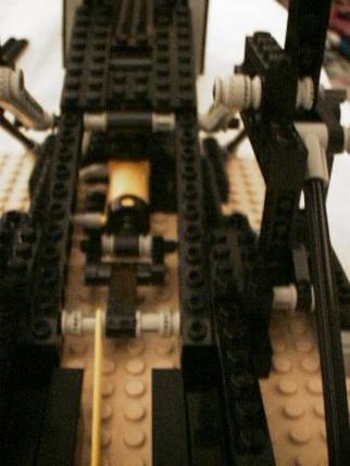
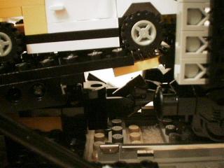
Another view, here the ramp pieces are all on, and the rack is extended to the train car's upper deck. You can see the extended rubber band as well. This is not a perfect solution as the rubber band pressure forces the plates of the ramp off their frame.
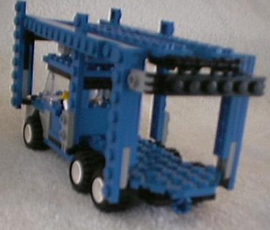
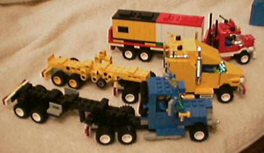
Taking a break from trying to figure out the rack levers, I did a blue tractor. I was still after a better tractor for the auto transport. I liked this tractor so much I put it into container service rather than cover it up. I think it looks a lot like a Mack(tm). Note that the mirrors really reflect, and there are digits on the rear license plate.. those are both from sticker edges (the part left after you apply a sticker to something). Is that pure? I'm not sure. Close to pure, though.
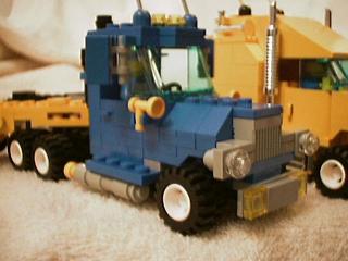
Look in the left (driver side for US residents) mirror, you can barely make out the minifig driver in the reflection.
I got inspired so I did some skeleton container trailers... (anything to avoid those darn lever throw calculations) after I finished the second one (yellow) I decided I had to get out one of my 2148s (none of which I had ever built) and press it into service too.. after a few mods to make it container hitch compatible, get the floorboards and front bumper right, I decided it looked like a Volvo (tm).
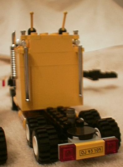
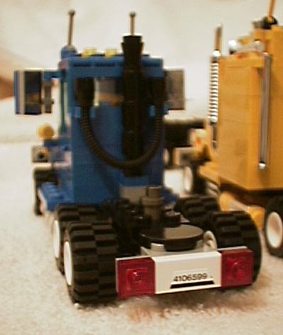
Note that both trailers have full width bumpers with separate red/yellow lights
and license plates. Both carry the <-O-> logo somewhere.
Against the wall you can see the gantries
of two 6339s and a 1682...
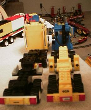
Here's the whole fleet... The 4549 container semi is shown for reference. the mack and volvo dwarf it.
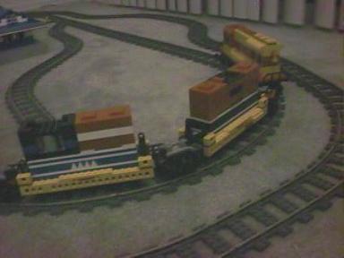
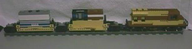
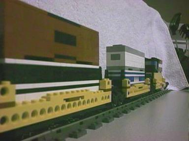
The first image shows the scale. My red/yellow engine and two units are arranged on a straight track. The two units have 5 containers (2 shorties and 3 regular length) between them
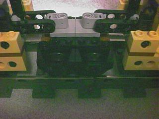
This image shows an end bogie/truck. One standard coupler is mounted at one end. There is a vertical technic stud (on 2x2 plate) that supports the unit end. I use a longer than normal set of beams so that I could put the pivot point well past center, to prevent bogie tipping. Downside of that is that it makes the truck/bogie track a bit funny. When all 5 units are present, they cannot be backed at high speed or over a very great distance, or over complex switch trackwork. This is prototypical, articulated cars typically are more sensitive to track flaws when being backed.
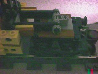
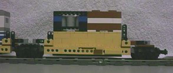
This image shows an end unit. The unit itself is asymmetrical, with a longer horizontal support bar/pivot on the coupler end. I mounted sign boards (which normally would carry a logo or reporting marks) low on the frame. Still not quite finished with the container tie downs but I do have the technic round end half or 1/3 beams in place ready for the tie down once I come up with a good design. These beams are the highest thing on the car itself (not including the containers).
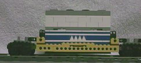
This image shows one of 4 mid unit bogies. The horizontal members coming in from the two units are identical. You can see how the basic car is engineered in this view. A 6xn plate forms the floor, very close to rail level (2-3 plates above it at most). The floor is held in place by the side beam assemblies. Each beam assembly has a pair of technic holes, spaced 5 plates apart (remember the magic Lego ratio) which pin into the pivot beam assembly. This assembly has the tie down bars, as well as the horizontal beams leading to the articulation point pivots on the bogies. It is 4 bricks in thickness, overall, and makes a good solid contact with the side beams.
The bottom container rests on tiles (some raised to mate with the container's end plates to prevent movement fore and aft) that are on the 6xn plates and is held from sideways movement by the side beams as well as the raised plates on the floor. You can clearly see the bottom container nestled between the beams in the next image. Prototype doublestacks look exactly like this. They are sometimes called "well cars" because the container sits in a well between the load carrying frame members. This is done to minimise the overall height of the car. Still, when doublestacks first came on the prototype scene, there was a flurry of clearance raising in the east. Many bridges and tunnels had to have their roofs or beams raised, or were removed completely.
Since the length of an assembly is longer than the longest technic beam, I had to use a long and short. In the 5 unit car, I have arranged them symmetrically. The middle unit has 2 1x2 beams. Each other unit uses 1 1x4 beam. That 1x4 is always facing the middle unit end of the unit. Just as on the prototype, the container sits in a well. The 6xn plates are not contributing (much) to the structural strength of the car.
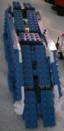
The following image gives an end view.
Here is a shot of the entire 5 unit car, on the layout. The car stretches all the way round a semicircle of track with some left over.
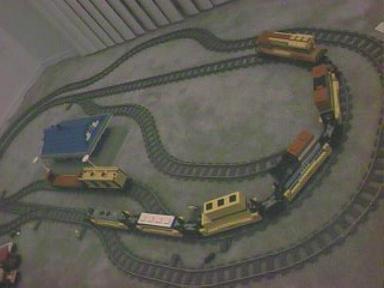
And here is a bit closer look.